
URL: https://flash.desy.de/accelerator/@@siteview
Breadcrumb Navigation
Accelerator
FLASH is DESY's free-electron laser user facility providing ultra-short femtosecond laser pulses in the EUV and soft-X ray wavelength range with unprecedented brilliance. FLASH is a high-gain free-electron laser (FEL) which achieves laser amplification and saturation within a single pass of a bunch of electrons through a long undulator. It does not require a set of mirrors which is needed in conventional lasers. The lasing process is initiated by the spontaneous undulator radiation. The FEL works then in the so-called Self-Amplified Spontaneous Emission (SASE) mode without needing an external input signal.
")
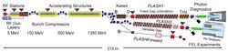
.Schematic layout of FLASH (not to scale). Beam direction is from left to right, the total length is 315 m. (Image: Siegfried Schreiber, DESY)
The electron bunches are produced in a laser-driven photoinjector and accelerated by a superconducting linear accelerator. The RF-gun based photoinjector allows the generation of electron bunches with tiny emittances - mandatory for an efficient SASE process. The superconducting techniques allows to accelerate thousands of bunches per second, which is not easily possible with other technologies.
At intermediate energies of 150 and 450 MeV the electron bunches are longitudinally compressed, thereby increasing the peak current from initially 50 to 80 A to 1 to 2 kA - as required for the lasing process in the undulator. The beam is then accelerated to 1.25 GeV, passing through a collimation section to scrape of unwanted beam halo.
Finally the beam enters the undulator. It is 27 m long and consists of permanent NdFeB magnets with a fixed gap of 12 mm, a period length of 27.3 mm and peak magnetic field of 0.47 T. The electrons interact with the undulator field in such a way, that so called micro bunches are developed. These micro bunches radiate coherently and produce intense X-ray pulses. Finally, a dipole magnet deflects the electron beam safely into a dump, while the FEL radiation propagates to the experimental hall.
FLASH emerged from the TESLA Test Facility (TTF) VUV-FEL.
On February 22nd, 2000 at 4:47 h, for the first time worldwide, lasing has been achieved with a SASE FEL at a VUV wavelength of 109 nm. The facility has been substantially upgraded in 2002/2003 and became FLASH.
The commissioning of FLASH started in 2004, and quickly succeeded in first lasing in the SASE mode at a wavelength of 32 nm. This was a major milestone of the facility and of SASE FEL's in general. In 2006, an energy upgrade pushed the wavelength down to 13 nm, a tremendous achievement.
Honoring this success, the FEL Prize 2006 has been awarded to E. L. Saldin and J. Roßbach: "..and so it became time to seriously consider the void in the spectrum that from the beginning all knew was there but that few people dared to dream about openly because the specifications for the electron beam seemed just outrageous. The FEL team at DESY nonetheless took up this challenge some ten years ago and set out to build an FEL that would produce 6 nm radiation. The impressive progress made, as was recently clearly demonstrated by FLASH, the 'demo' for the big X-FEL laser under development in Hamburg, that pushed the short wavelength limit for lasing down to only 13 nm(!), proves beyond doubt the great potential of FELs for the x-ray regime."
In 2007, the design wavelength of 6.5 nm has been achieved - another world record at that time. In 2009/2010, the accelerator has again been significantly upgraded. The accelerator has been extended by a seventh accelerating module and by four superconducting cavities operating at 3.9 GHz to linearize the longitudinal electron beam phase space. A linear correlation of the electron energy along the bunch is important for efficient compression to the kilo-Ampere level. The new configuration pushes the electron beam energy up to 1.25 GeV allowing lasing at 4.1 nm and thus entering into the water window.
In 2012, the construction of a second beamline, FLASH2 has started and finished early 2014. The long trains of electron bunches of FLASH are split in two - such that one part serves the old FLASH1 beamline, the other part the new FLASH2 beamline, both with the 10 Hz repetition rate of the acceleartor. This allows to almost double the time for scientific experiments.
FLASH is also a pilot facility for the European XFEL project and a test bed for further research and development for linear collider related superconducting accelerator technologies.

")
Figure 2: Wavelength as a function of beam energy. Since FLASH1 has a fixed gap undulator, a change of wavelength is obtained by changing the energy of the electron beam. Shown are also various milestones toward short wavelength operations.
The LINAC
Injektor
Based on the experience with the TTF phase 1 injector, the injector of the TESLA test facility has been redesigned to meet the tighter demands on the electron beam quality for FLASH. The design follows the proposal for the European XFEL. The performance of the injector is crucial for the successful generation of FEL radiation. For this reason, a photoinjector test facility (PITZ) has been set-up to optimize electron sources for FELs and other applications. The injector has been successfully commissioned in the first half of 2004. Most important parameters are: generation of trains of electron bunches with a charge of 20 pC to 1 nC each, and a normalized transverse emittance of less than 2 µm rad. The bunch train length of 800 µm and the repetition rate of 10 Hz are adapted to the superconducting TESLA accelerating structures. A normal conducting laser-driven photocathode RF gun provides rapid acceleration from the cathode and allows to generate a low emittance beam from the source.
The RF gun and the laser system have been successfully tested and optimized at PITZ and installed at FLASH in January 2004. The RF gun is a 1 1/2 cell L-band cavity (1.3 GHz, TM010 mode) powered by a 10 MW klystron. A longitudinal coupler is used to keep the cylindrical symmetry around the beam axis as perfect as possible. The RF gun is presently operated with an RF power of 4.5 MW - corresponding to a maximal accelerating field gradient of 50 MV/m on the cathode. The RF pulse length is up to 0.83 ms at a repetition rate of 10 Hz. Usually the gun is operated with 0.5 ms pulse length.
A low level RF system based on the MTCA.4 standard reads the forward and reflected power to and from the gun and regulates the RF power and RF phase by acting on the
low level RF input to the klystron amplifier. The phase stability goal is 0.01 dg, the amplitude stability 0.01%.
A Cs2Te photocathode is inserted into the RF gun backplane via a load-lock system and can be changed if required. The cathode quantum efficiency achieved (for UV light) is initially high (more than 10%) and drops slowly to a comfortable level of 3% after several months of usage.
The main laser is based on a pulsed mode-locked pulse train oscillator synchronized to the 1.3 GHz RF of the accelerator. The phase stability is better than 100 fs rms. A chain of linear Nd:YLF amplifiers provides the laser pulse energy of up to 100 µJ to convert the initial infrared wavelength into UV (262 nm). The system produces pulse trains with up to 800 µs length at a repetition rate of up to 10 Hz. The pulse spacing is usually 1 µs (1 MHz). A rate of 3 MHz at 5 Hz is also possible. Other intra-train bunch frequencies are realized frequently, like 500 kHz, 250 kHz, 200 kHz, 100 kHz, 50 kHz, and 40 kHz.The charge fluctuation of a single electron bunch from shot to shot is better than 0.5% rms. The pulses duration in the UV measured with a streak camera is 4.6±0.1 ps corresponding to an electron bunch length of about 2 mm.
A second laser system with simiar parameters used for FLASH2 and a third system able to produce shorter pulses of about 1 ps is availbe as well.
After the electron beam is generated in the RF gun, a TESLA type module with eight superconducting accelerating structures boosts the beam energy to 150 MeV. Here, the first bunch compression takes place. With the digital feedback system regulating the phase and amplitude of the accelerating structures, the energy stability dE/E is better than 0.5·10-4 and the phase stability better than 0.01 dg rms.
The uncompressed rms bunch length has been measured with a streak camera to be 1.7±0.2 mm as expected. A small transverse emittance of less than 2 µm rad normalized at a charge of 1 nC is achieved by two measures. A solenoid (0.18 T) compensates the emittance growth induced by space charge in the drift after the gun. The beam optics is then matched to the theoretical optics for further acceleration.
Four superconducting cavities operating at 3.9 GHz, the third harmonics of 1.3 GHz, are installed downstream of the first booster module but before the bunch compressor. They allow to manipulate the longitudinal phase space to a certain extend. Properly used, the energy-time correlation in the electron bunch is linearized allowing a perfect compression of the bunch in the following two compression stages.

")
FLASH Photoinector. The RF gun itself is covered by the blue solenoid magnets. Part of the load-lock system to insert cathodes is visible in the lower left part. Rectangular waveguides feed the High power RF through an RF-window to the gun. The round transferline for superfluid Helium is attached to the first acceleration module.
Bunch compressors
The peak current of the uncompressed bunch is about 70 A. In order to achieve a final peak current exceeding 2 kA, a compression of the bunch using magnetic chicanes is done in two steps at energies of 150 MeV and 450 MeV. Care is taken to avoid an unacceptable emittance growth due to space charge, wakefield, and coherent synchrotron radiation effects. The rms bunch length in the first accelerating section before compression is long compared to the RF wavelength (about 2 mm or 3 dg in RF). The beam is accelerated about 10 dg off-crest in order to impose an energy chirp along the bunch for compression. Due to the length of the bunch and the sinusoidal RF field, a curvature in the energy-phase plane develops. The compression with the imposed curvature leads to a bunch with a sharp high current spike and a long tail (spike length 50 to 100 fs).
To linearize the energy chirp, four superconducting third harmonic cavities (3.9 GHz) are installed before the first bunch compressor. With these cavities a flexible tailoring of the longitudinal phase space is possible.
Diagnostics
The linac includes a large variety of diagnostic tools to measure the transverse and longitudinal beam properties, beam positions, current etc. Remarkable results have been achieved in the measurements of the transverse projected emittance and the longitudinal bunch structure. The transverse beam size is measured using optical transition radiators (OTR). Twenty-four stations with movable radiators are installed, equipped with a high resolution imaging system each. An impressively small transverse emittance for the uncompressed beam is measured in the injector at 127 MeV. The normalized projected rms emittance for a 1 nC bunch is 1.4 µm rad. For this analysis, 90% of the bunch intensity is used, the statistical error is 4%, the systematic error estimated with 6%.
A powerful method to measure the bunch length is the deflecting cavity LOLA. The S-band deflecting cavity has a length of 3.66 m and has been provided by our colleagues from SLAC. LOLA is installed just upstream of the undulator. A kicker allows to select an arbitrary bunch of the electron pulse train. This bunch is streaked by LOLA onto a special screen. The bunch length information is available on-line during runs.The resolution of the system is better than 10 µm or 10 fs in terms of bunch duration. LOLA can also be used in combination with a dispersive section. This allows a single shot measurement of the longitudinal phase space of the first bunch in then train.
Undulators
A single pass high gain FEL requires a long undulator system. The FLASH system consists of six undulator modules with a length of 4.5 m each. The fixed gap is 12 mm with a peak magnetic field of 0.48 T (K=1.23) realized with permanent NdFeB magnets. The undulator period is 27.3 mm. In terms of FEL radiation it covers the wavelength range of 120 to 4 nm.
A pair of electromagnetic quadrupoles between each of the six modules provides a large acceptance in beam energy. . Each quadrupole doublet is aligned on a stable granite base plate together with beam position monitors and a vertical and horizontal wirescanner. The absolute alignment in respect to the undulator axis is better than 100 µm. The SASE process requires an alignment of the electron beam with the undulator axis of better than 10 µm. Therefore, the quadrupoles are equipped with movers allowing a fine adjustment of their position.
A collimation section protects the undulators from radiation due to off-energy and off-orbit particles. The design includes two copper collimators in the straight and two in a dogleg section allowing to collimate off energy particles as well. The energy acceptance is ±3%.

")
FLASH2 variable gap undulators.
Photon diagnostics
A diagnostic section is located in the FEL beam line to measure the properties of the FEL radiation. An important instrument for tuning the onset of laser amplification and optimizing the lasing is a detector based on gold wires and a micro-channel plate (MCP). The dynamic range of this detector is sufficient to cover several orders of magnitude of radiation energy, from spontaneous (7 nJ for 1 nC) to the amplified emission (50 to 1000 µJ). The absolute number of photons is measured with gas monitor detectors. Over a large dynamic range, they have an absolute measurement uncertainty of 25% only. Different Noble gases are used to cover the whole wavelength range of FLASH. View screens using Ce:YAG crystals are placed at various locations. A monochromator is used to measure single shot spectra. It is equipped with an intensified CCD camera and has a resolution of 0.02 nm with an absolute calibration error of less than 0.03 nm.
Experimental Halls
The FLASH1 experimental hall "Albert Einstein" is presently equipped with five experimental stations. A variety of experiments in basic and applied research of multiple scientific fields, from life science, chemistry to physics are scheduled including pump-probe experiments.
The FLASH2 experimental hall "Kai Siegbahn" is being set-up with beamlines for experiments. A fixed end-station, REMI. has already been in operation for users.
FLASH1 |
FLASH2 |
||
Electron beam |
|||
|---|---|---|---|
Energy |
MeV |
0.35 - 1350 |
0.4 - 1350 |
Peak current |
kA |
1 - 2.5 |
1 - 2.5 |
Emittance, norm, at 0.4 nC |
µm rad |
0.4 |
0.4 |
Electron bunches per second |
5000 |
5000 |
|
bunch train duration (max) |
ms |
0.8 |
0.8 |
Rep. rate |
Hz |
10 |
10 |
Energy spread |
keV |
200 |
500 |
Undulators |
|||
Period |
cm |
2.73 |
3.14 |
Gap |
mm |
12 |
9 |
Peak magnetic Field |
T |
0.48 |
variable |
K |
1.2285 |
1.0 - 2,7 |
|
total length |
m |
6 * 4.5 |
12 * 2.5 |
FEL radiation |
|||
Wavelength |
nm |
3.4 - 51 |
3.3 - 90 |
Single Pulse Energy |
µJ |
1 - 500 |
1 - 1000 |
Average Power |
mW |
<1000 |
<1000 |
Spectral width (fwhm) |
% |
0.7 - 2 |
0.5 - 2 |
Pulse Duration (fwhm) |
fs |
30 - 200 |
10 - 200 |
Peak Power |
GW |
1 - 5 |
1 - 5 |
Photons per Single Pulse |
1011 - 1014 |
1011 - 1014 |
|
Peak Spectral Brilliance |
photons/s/mrad² /mm² /(0.1% bw) |
1028 - 1031 |
1028 - 1031 |

")